
OBD Port Inspection Before ECU Programming: A Professional Checklist
When a vehicle ECU cannot be identified through OBD, the programming tool is not always the cause. A damaged diagnostic connector, loose terminal, contamination or missing power supply can interrupt communication before the ECU programmer reaches the control unit.
A professional OBD port inspection should be completed before replacing cables, changing software or selecting another protocol. Checking the connector helps technicians separate a vehicle-side wiring issue from an ECU, tool or software problem.
Why the OBD Connector Matters
The OBD connector provides access to the vehicle diagnostic network and may also provide power and ground for the connected tool. Several terminals work together to support communication, so one damaged or loose contact can create a complete no-communication symptom.
A faulty OBD connector may cause:
- The programming tool does not power on.
- The vehicle identification cannot be read.
- Communication starts and then stops.
- The tool disconnects when the cable moves.
- Several unrelated ECUs appear unavailable.
- Diagnostic fault codes are stored in gateway or body modules.
Because the connector is often located under the dashboard, it can be exposed to dust, impact, moisture, aftermarket accessories and repeated cable stress.
1. Locate the Correct Diagnostic Connector
Most vehicles place the OBD connector in the driver’s lower dashboard area, but the exact location can vary. Some vehicles use covers, extensions or additional diagnostic connectors.
Before testing, confirm:
- That the connector is the correct diagnostic port for the vehicle
- That no aftermarket adapter remains plugged in
- That the connector housing is securely mounted
- That the terminals have not been pushed behind the housing
- That the vehicle documentation matches the connector layout
Never force a programming cable into a connector that does not align correctly. A bent terminal can create a more serious wiring problem.
2. Inspect the Connector Housing
Begin with a visual inspection using a flashlight. Look for damage that may prevent the cable from seating fully.
- Cracked or loose plastic housing
- Missing connector cover
- Broken mounting bracket
- Foreign objects or debris
- Moisture or corrosion marks
- Signs of impact from a previous tool connection
- Aftermarket wiring spliced into the connector
A connector that moves inside the dashboard can place stress on the wiring harness and cause intermittent communication.
3. Check the Terminal Condition
OBD terminals should be straight, clean and positioned at the correct depth. A terminal that is recessed or spread may not make reliable contact with the programming cable.
Check for:
- Bent terminals
- Recessed terminals
- Loose terminal tension
- Green, white or dark corrosion
- Burn marks or heat discoloration
- Contamination from liquids or cleaning products
Do not insert sharp objects into the connector to bend terminals into place. Use the correct terminal repair method and avoid shorting adjacent circuits.
4. Confirm OBD Power and Ground
The diagnostic connector may provide the programmer with power and a reference ground. If power or ground is missing, the tool may appear defective even when the cable and programming software are working correctly.
Under the correct vehicle conditions, verify:
- Diagnostic connector power supply
- Ground terminal continuity and quality
- Fuse protection for the diagnostic socket
- Power behavior with the cable connected
- Any voltage drop caused by a loose terminal
Use the wiring information for the exact vehicle. Do not assume that every vehicle uses identical terminal assignments or power behavior.
5. Inspect the Cable Plug
An OBD port problem can be confused with a damaged cable plug. Inspect both sides of the connection before drawing a conclusion.
Look for:
- Broken or displaced plug terminals
- Damaged strain relief
- Excessive movement inside the plug
- Contamination on the contacts
- Cracked housing
- Signs of overheating
Connect the cable straight into the port without twisting it. If communication changes when the cable is lightly supported, stop the operation and inspect the connector tension and harness.
6. Check for Aftermarket Wiring
Vehicles may have tracking devices, alarms, remote starters, insurance modules or other accessories connected near the diagnostic network. Poorly installed equipment can interfere with power, ground or communication.
Record and inspect:
- Non-original wires near the OBD connector
- Scotch-lock or crimp connections
- Additional plugs or extension harnesses
- Loose grounds under the dashboard
- Devices that remain connected during programming
Do not disconnect unfamiliar equipment without understanding its purpose. Document the setup and follow the vehicle owner’s service requirements.
7. Confirm the Vehicle State Before Testing
OBD communication depends on the vehicle’s ignition, gateway and network state. A correct connector may appear inactive if the vehicle is asleep or if the required ignition condition has not been selected.
Before starting identification:
- Confirm the vehicle battery and electrical system are in the required condition.
- Set the ignition according to the vehicle or protocol procedure.
- Close unnecessary vehicle systems.
- Avoid moving the key, doors or diagnostic cable during the session.
- Wait only for the time specified by the applicable procedure.
Do not switch ignition states repeatedly while the programming software is communicating with the ECU.
8. Separate OBD Port Problems from ECU Problems
If the OBD port has correct power and ground but the ECU cannot be identified, continue with a structured diagnosis. Check whether another control unit communicates through the same connector and whether the selected ECU is listed as supported.
Possible causes outside the connector include:
- Incorrect vehicle or ECU selection
- Unsupported OBD function
- Gateway communication problem
- ECU power or ground failure
- Incorrect operation mode
- Vehicle network fault
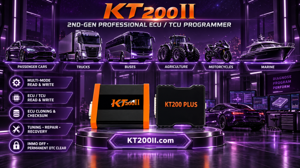
The KT200II supported ECU and TCU list can be used to confirm whether the vehicle, ECU type, requested function and OBD connection are supported.
9. Confirm the Correct Programming Mode
Not every ECU that can be diagnosed through a vehicle connector can be programmed through OBD. Some supported control units require direct Bench, Boot, JTAG or BDM access.
Review the KT200II operation modes guide to understand the connection requirements for each supported mode. Do not select a different mode simply because the OBD connector appears functional.
| Observation | Possible Direction |
|---|---|
| Tool has no power | Check connector power, ground and fuse protection |
| Tool powers on but no ECU is identified | Check vehicle state, protocol and ECU support |
| Communication changes when cable moves | Inspect terminal tension, plug and harness |
| Other modules communicate but target ECU does not | Check target ECU power, gateway path and selected function |
| OBD is not listed for the ECU | Check whether Bench or another supported mode is required |
10. Record the OBD Inspection
Professional workshops should record the connector condition and test results. This information helps if the vehicle returns with an intermittent communication complaint.
Include:
- Vehicle and ECU identification
- OBD connector condition
- Power and ground test results
- Fuse condition
- Aftermarket wiring observations
- Selected protocol and operation mode
- Software message or error code
- Final communication result
OBD Port Inspection Checklist
- Correct diagnostic connector confirmed
- Housing and mounting checked
- Terminals inspected for corrosion and damage
- Power and ground verified
- Diagnostic fuse checked
- Cable plug inspected
- Aftermarket devices documented
- Vehicle ignition and network state prepared
- ECU support and OBD function confirmed
- Inspection results saved in the job record
Frequently Asked Questions
Can a damaged OBD port prevent ECU programming?
Yes. A missing power supply, weak ground, bent terminal or unstable communication contact can prevent the programming tool from identifying the ECU.
Why does the programming tool power on but fail to find the ECU?
The tool may receive power while the communication path remains faulty. Check the vehicle state, ECU support, protocol, gateway and target ECU power.
Can I bend an OBD terminal back with a metal tool?
Avoid using sharp metal objects inside the connector. Incorrect handling can short terminals or cause additional damage. Use an approved terminal repair method.
Where can I download the official programming software?
Review the official KT200II software download page for available software packages and supported Windows systems.
Conclusion
A careful OBD port inspection can prevent unnecessary cable replacement, protocol changes and repeated programming attempts. Check the connector housing, terminal condition, power, ground, fuse protection, cable plug and vehicle network state before starting ECU programming.
For official ECU and TCU programming information, visit the KT200II product page. More practical ECU programming guidance is available on the KT200II technical blog.
For package and purchase information, visit the official KT200II store page.