ECU Diagnosis and Troubleshooting: Common Problems and Professional Repair Methods
The Engine Control Unit (ECU) is one of the most important electronic components in modern vehicles. It processes information from multiple sensors and controls essential engine functions, including fuel injection, ignition timing, turbocharger operation and emissions management.
When an ECU develops a fault, the vehicle may experience starting problems, poor engine performance, communication failures or unexpected warning lights. Professional ECU diagnosis helps technicians identify the actual source of these problems and determine whether the issue is related to wiring, sensors, software or the control module itself.
1. What Is ECU Diagnosis?
ECU diagnosis is the process of examining an engine control unit and its connected electronic systems to identify faults and abnormal operating conditions.
Modern diagnostic procedures typically involve several types of testing:
- Reading diagnostic trouble codes (DTCs).
- Checking ECU power supply and ground connections.
- Testing communication networks.
- Monitoring live sensor data.
- Checking wiring and electrical signals.
- Verifying ECU software and configuration.
- Performing supported module communication tests.
Accurate diagnosis requires more than simply reading fault codes. Technicians must understand how the ECU interacts with sensors, actuators and other vehicle control modules.
2. Common Symptoms of ECU Problems
ECU-related faults can produce different symptoms depending on the affected circuit, software function or internal hardware component.
Engine Starting Problems
A vehicle may fail to start if the ECU cannot receive essential sensor signals, control fuel injection or communicate with other required electronic modules.
Unstable Engine Performance
Incorrect sensor information, wiring problems or control module faults may cause rough idling, hesitation, reduced power or unexpected engine behavior.
Communication Failure
If a diagnostic tool cannot establish communication with the ECU, the problem may involve power supply, ground, CAN communication, wiring or the ECU itself.
Warning Lights and Fault Codes
Repeated warning lights or diagnostic trouble codes may indicate problems in engine management circuits, sensor systems or communication networks.
Unexpected Limp Mode
Some vehicles activate a reduced-performance mode when the ECU detects conditions that may threaten engine or transmission reliability.
3. Checking ECU Power Supply and Ground
Before investigating internal ECU hardware problems, technicians should verify that the control module receives the correct electrical supply.
Important checks include:
- Battery voltage and stability.
- Permanent ECU power supply.
- Ignition-switched power supply.
- ECU ground connections.
- Fuse and relay conditions.
- Connector corrosion or damaged terminals.
A weak battery, damaged ground connection or faulty relay can create symptoms that appear to be an internal ECU failure.
Voltage measurements should be performed using appropriate electrical testing equipment and the vehicle manufacturer's specifications.
4. Diagnosing CAN Bus Communication Problems
Modern vehicles use communication networks to exchange information between electronic control modules. CAN bus is one of the most widely used automotive communication systems.
Communication faults can prevent the ECU from exchanging information with the instrument cluster, transmission controller, ABS module and other vehicle systems.
Common causes include:
- Damaged CAN-H or CAN-L wiring.
- Short circuits between communication lines.
- Incorrect network termination.
- Corroded connectors.
- Faulty electronic control modules.
- Network configuration problems.
Technicians should use the correct wiring diagram and diagnostic procedures when investigating CAN communication faults. Resistance and voltage measurements must be interpreted according to the specific network architecture.
5. Using Live Data for ECU Troubleshooting
Live data is an important diagnostic resource because it allows technicians to observe sensor values and ECU operating parameters in real time.
Depending on the vehicle, useful live data may include:
- Engine speed.
- Coolant temperature.
- Intake air temperature.
- Mass air flow.
- Manifold pressure.
- Throttle position.
- Fuel rail pressure.
- Oxygen sensor readings.
- Accelerator pedal position.
Comparing live data with expected operating values can help identify sensor faults, wiring problems and abnormal engine management conditions.
For example, an incorrect coolant temperature reading may affect fuel enrichment and engine operating strategies. However, technicians should confirm the sensor, wiring and reference voltage before concluding that the ECU is defective.
6. ECU Internal Hardware Problems
When external electrical circuits and communication systems have been checked, internal ECU hardware may need further investigation.
Common internal problems can include:
- Damaged voltage regulation circuits.
- Failed electronic components.
- Corrosion caused by moisture intrusion.
- Damaged communication transceivers.
- Defective driver circuits.
- Cracked solder joints.
- Overheating-related component damage.
Professional ECU repair may require electronic measurement equipment, component-level testing and appropriate technical documentation.
Opening and testing a control module should only be performed by technicians with suitable electronics repair experience.
7. ECU Software and Memory Problems
Not every ECU problem is caused by damaged hardware. Software corruption, incomplete programming and incompatible data can also affect module operation.
Potential software-related issues include:
- Interrupted ECU programming.
- Incorrect software files.
- Incomplete Flash writing.
- Memory data corruption.
- Checksum errors.
- Incompatible software versions.
When software problems are suspected, technicians should first identify the exact ECU hardware and software numbers. Original data should be backed up whenever possible before attempting supported recovery procedures.
8. ECU Diagnosis Using OBD, Bench and Boot Modes
Different diagnostic and programming methods provide different levels of access to electronic control modules.
OBD Diagnosis
OBD communication allows technicians to access supported vehicle systems through the diagnostic connector. It is commonly used for fault code reading, live data monitoring and supported ECU programming operations.
Bench Testing
Bench testing involves connecting an ECU directly to diagnostic or programming equipment outside the vehicle.
This method can help technicians investigate communication problems, verify module operation and perform supported memory operations without relying on the complete vehicle network.
Boot Mode Access
Boot mode provides specialized access to supported ECU architectures. Depending on the control unit, it may allow specific memory reading, writing or recovery operations.
Not every ECU supports the same diagnostic or programming functions. Always verify the exact protocol and connection requirements.
9. A Professional ECU Troubleshooting Workflow
A structured diagnostic workflow helps reduce unnecessary component replacement and improves repair efficiency.
- Identify the vehicle: Record the manufacturer, model, engine and ECU identification.
- Read fault codes: Retrieve DTCs from the engine ECU and related modules.
- Check electrical supply: Verify battery voltage, ECU power and ground.
- Inspect communication: Check diagnostic communication and network wiring.
- Analyze live data: Compare sensor readings with expected operating conditions.
- Inspect wiring: Check connectors, terminals and damaged circuits.
- Evaluate ECU hardware: Investigate internal faults when external causes have been excluded.
- Verify software: Check module identification, memory integrity and programming history where available.
- Perform final testing: Confirm communication, clear resolved faults and verify vehicle operation.
10. Choosing Professional ECU Diagnostic Equipment
Reliable diagnostic equipment is essential for modern automotive electronics workshops.
When selecting an ECU diagnostic and programming solution, technicians should consider:
- Vehicle and ECU coverage.
- Diagnostic communication capabilities.
- OBD, Bench and Boot support.
- Flash and EEPROM reading capabilities.
- Supported ECU recovery operations.
- Wiring diagrams and connection documentation.
- Software updates and technical support.
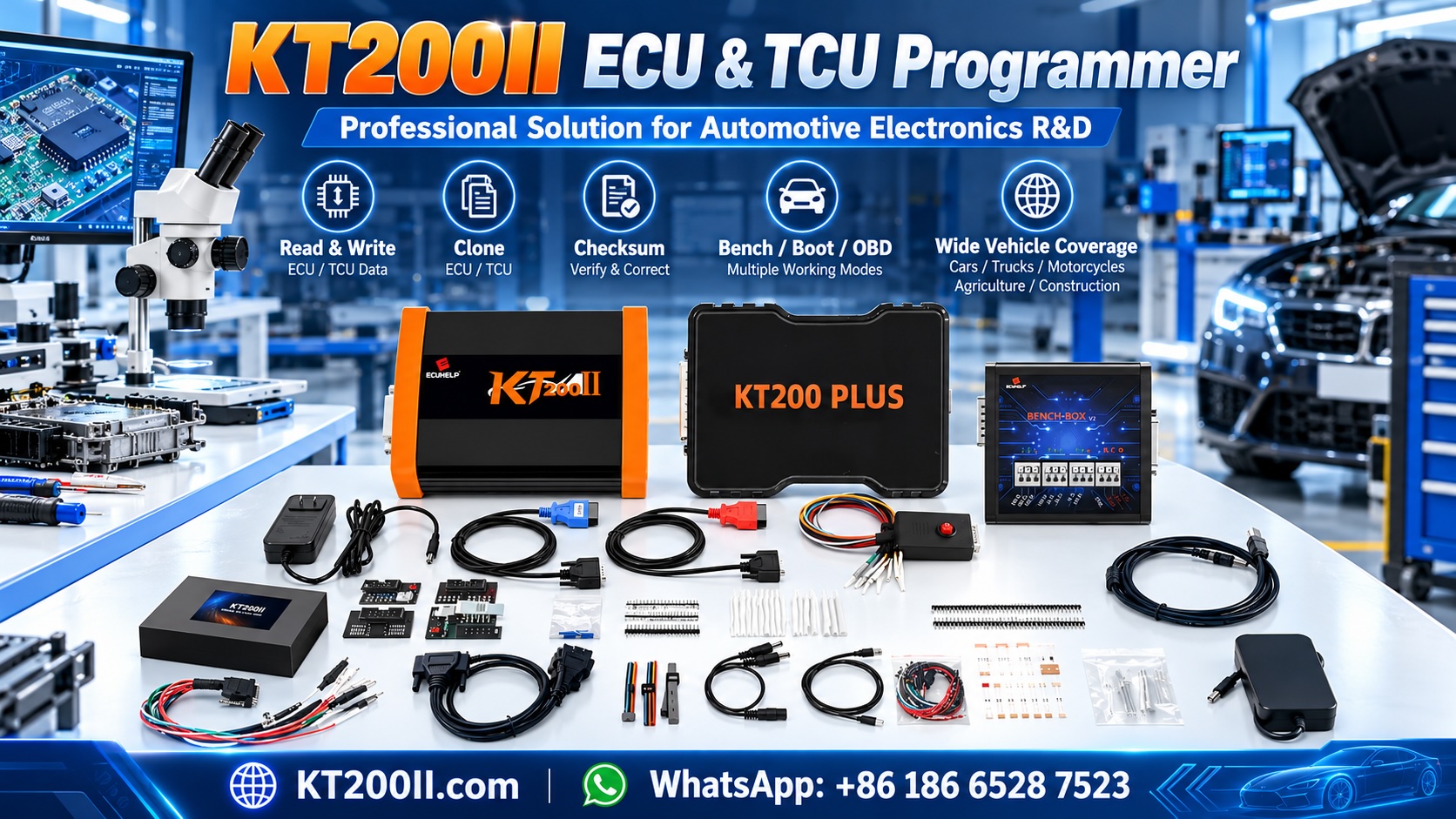
A professional programming tool can support more advanced repair workflows, but its capabilities must always be checked against the exact ECU hardware and software version.
Visit AutoECUMaster to explore automotive ECU programming equipment and electronic control module solutions.
11. Preventing Future ECU Problems
Although not every ECU failure can be prevented, proper vehicle maintenance and electrical practices can reduce unnecessary risks.
- Maintain a healthy vehicle battery.
- Inspect charging system performance.
- Repair damaged wiring promptly.
- Prevent water intrusion into ECU housings and connectors.
- Use appropriate power supplies during programming.
- Follow manufacturer programming procedures.
- Keep original ECU data backups when performing supported operations.
- Avoid installing incompatible electronic components.
12. Conclusion
ECU diagnosis is an essential part of modern automotive repair. Problems involving power supply, communication networks, sensors, internal hardware and software can all affect engine control module performance.
Accurate troubleshooting requires a systematic approach that combines fault code analysis, electrical testing, live data monitoring and appropriate programming equipment.
By identifying the actual source of a problem before replacing or reprogramming components, professional technicians can improve repair accuracy, reduce unnecessary costs and provide more reliable automotive electronic services.
For more information about ECU programming and automotive electronics solutions, visit AutoECUMaster.