
Vehicle Ignition State Checklist Before ECU Programming
Before starting an ECU programming operation, technicians often focus on the vehicle model, ECU number, software selection, and communication cable. However, the vehicle ignition state is equally important. A control unit may fail to identify correctly when the ignition position, key status, battery support, or vehicle network condition is not prepared correctly.
This vehicle ignition state checklist provides a practical starting procedure for automotive workshops performing OBD diagnostics, ECU reading, ECU writing, cloning, configuration, or post-programming verification.
Why Ignition State Matters
Different vehicles use different ignition logic. Some vehicles require the ignition to be switched on without starting the engine. Others may require a specific key position, a smart key inside the vehicle, a start button pressed without the brake pedal, or a short waiting period before the modules become fully active.
If the ignition state is incorrect, the programming interface may show symptoms such as:
- No communication with the selected ECU.
- Incomplete vehicle identification.
- Repeated connection or authorization prompts.
- Unexpected sleep or wake-up behavior.
- Communication loss during a diagnostic check.
Vehicle Ignition State Checklist
| Inspection Area | What to Confirm | Recommended Action |
|---|---|---|
| Ignition position | The key or start button is in the position required by the vehicle procedure. | Follow the vehicle-specific instructions before starting communication. |
| Engine status | The engine is stopped unless the procedure specifically requires it to run. | Do not start the engine during an active read or write operation. |
| Key or smart key | The correct key is present and recognized by the vehicle. | Keep the key in the required location and remove unrelated keys. |
| Battery support | Vehicle voltage can remain stable throughout the operation. | Connect approved battery support when required by the programming procedure. |
| Accessories | Lights, climate control, audio, chargers, and other loads are controlled. | Switch off unnecessary electrical consumers. |
| Vehicle network | Doors, hood, alarm, and sleep-mode conditions are managed. | Prevent the vehicle from entering an unexpected sleep or security state. |
1. Confirm the Correct Ignition Position
Identify whether the procedure requires ignition off, accessory mode, ignition on, or another specific position. In many cases, the engine should remain stopped while the ignition is switched on. On push-button vehicles, the required sequence may involve pressing the button without pressing the brake or clutch pedal.
Do not assume that the same ignition sequence applies to every vehicle in the same brand. Model year, key system, body controller, and ECU family can affect the required state.
2. Check the Key or Smart Key Status
For vehicles with an immobilizer or smart-key system, confirm that the correct key is available and recognized. Keep the key inside the vehicle or near the approved detection area when the procedure requires it.
Remove unrelated keys, aftermarket transmitters, and wireless devices from the immediate area when they may interfere with the vehicle’s normal authorization process. If the instrument cluster displays a key warning, resolve that condition before beginning ECU programming.
3. Control the Engine and Electrical Loads
Unless the manufacturer procedure specifically requires the engine to run, keep the engine stopped during ECU identification, reading, writing, and verification. Switch off the air conditioner, headlights, audio system, seat heating, chargers, and other unnecessary loads.
Close the doors and hood according to the vehicle procedure. Some vehicles may enter sleep mode when a door is locked, while others may keep modules awake when the hood is open. Use the service instructions for the specific vehicle instead of relying on a general assumption.
4. Stabilize Vehicle Voltage
An ignition-on vehicle can consume power even when the engine is not running. Before connecting a programming interface, check the battery condition and confirm that the voltage is suitable for the planned operation.
When battery support is required, use a stable and approved power supply. Confirm its connection before starting the programming software. The power supply should not be adjusted or disconnected during an active operation unless the approved recovery procedure specifically requires it.
Voltage stability is especially important during ECU writing and configuration. A correct ignition state cannot compensate for a weak battery, loose terminal, or unsuitable support unit.
5. Allow the Vehicle Network to Wake Up
Some vehicles need several seconds after ignition is switched on before all relevant control units become available. Observe the instrument cluster and allow warning lamps or network messages to settle before starting communication.
If the vehicle has recently been locked, unlocked, connected to a battery charger, or subjected to a diagnostic scan, allow the system to complete its normal wake-up sequence. Avoid repeatedly switching the ignition on and off while the programming interface is attempting to identify the ECU.
6. Verify the OBD Connection and Programming Method
For OBD work, inspect the diagnostic socket and confirm that the connector is fully seated. Check for loose terminals, aftermarket accessories, or physical damage that could affect communication.
For KT200II applications, review the official KT200II Support List before starting. Confirm that the vehicle, ECU family, and required protocol match the selected job.
Review the KT200II Operation Modes page when deciding whether the application requires OBD, Bench, Boot, JTAG, or BDM. A vehicle ignition checklist is mainly used for vehicle-side communication, while bench and boot procedures may use a different power and activation sequence.
7. Record the Initial Vehicle State
Write the ignition position, key status, battery support setting, dashboard warnings, and vehicle mileage or identification details in the job record. Recording the initial state helps technicians compare the vehicle condition before and after programming.
If the software displays an identification result, save it with the job files. The original read file and related records should remain unchanged so that the technician can trace the complete operation later.
Official KT200II References
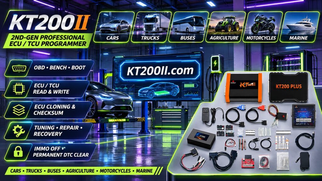
The official website for the KT200II ECU programmer is KT200II.com. The official global store is HELPECU.com.
For product information, visit the KT200II Product page. Software resources are available on the KT200II Software page, and additional ECU programming guides are available through the KT200II Blog.
Final Pre-Programming Check
- Confirm the correct ignition position.
- Make sure the correct key or smart key is recognized.
- Keep the engine stopped unless the procedure requires otherwise.
- Switch off unnecessary electrical loads.
- Stabilize vehicle voltage with approved battery support.
- Allow the vehicle network to wake up normally.
- Inspect the diagnostic socket and interface connection.
- Confirm the vehicle and ECU application in the support information.
- Record the initial vehicle state before Read or Write.
Conclusion
Confirming the vehicle ignition state before ECU programming is a small step that can prevent communication problems and confusing diagnostic results. The correct key position, stable voltage, controlled electrical loads, and proper vehicle wake-up sequence create a more reliable starting condition.
Use this checklist together with the vehicle service procedure, the correct programming mode, the supported application information, and the software instructions. A controlled beginning makes the rest of the ECU programming workflow easier to verify and document.